GASRATS Overview
The Get Away Special Radio and Antenna Transparency Satellite (GASRATS) is a 3U CubeSat education and technology demonstration mission focused on developing and demonstrating an optically transparent S-band patch antenna that can be integrated atop a commercially purchased solar panel in low-Earth orbit. The satellite is developed in collaboration with USU professor Dr. Reyhan Baktur in the USU Electrical and Computer Engineering Department.
The operational objectives of GASRATS will test the performance of the transparent patch antenna while exposed to the conditions of low-Earth orbit. Testing performed by GASRATS will help potential future users of the transparent patch antenna determine the suitability of the technology for their mission.
The GASRATS mission offers the opportunity for USU students to design, manufacture, and operate a CubeSat. GASRATS will also feature a statewide outreach program to inspire and educate Utah K-12 students known as the Bring Utah Students to Space Program.
GASRATS is expected to launch in 2026 through NASA's CubeSat Launch Initiative (CSLI).

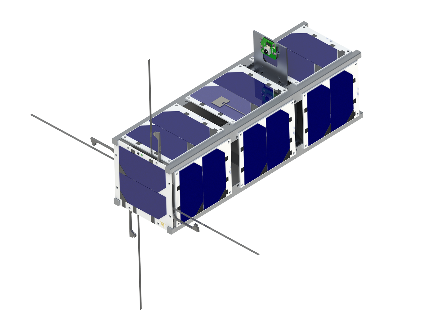
GASRATS Render
GASRATS Objectives
The objectives of the GASRATS mission are:
- Demonstrate the capability of an optically transparent solar panel-integrated S-band patch antenna to downlink in the space environment
- Analyze physical changes of the transparent patch antenna in the space environment
- Measure how the impact the transparent patch antenna has on solar panel power generation increases over time due to the space environment
Transparent Patch Antenna
The main payload of GASRATS is the novel Transparent Patch Antenna (TPA). The TPA integrates onto a solar panel, allowing GASRATS high-bandwidth communication while preserving solar panel coverage, a benefit that traditional patch antennas cannot provide. The TPA is manufactured by printing and baking silver-nitrate ink on a transparent substrate. The TPA is being developed in collaboration with Dr. Reyhan Baktur, whose research in CubeSat antenna design is the basis for the TPA.

Meshed TPA prototype on film substrate
Solar Panel Integration
Patch antennas require external placement on the satellite, generally causing CubeSats to forgo a solar panel when integrated. The optically transparent antenna, however, is attached to the outside face of a solar panel, allowing power generation from the solar panel beneath the antenna.
The TPA has a mesh structure to allow light through. The mesh can be optimized to offer the greatest transparency for the necessary gain. The patch antenna for GASRATS is planned to have greater than 90% transparency.

Early TPA prototype on a solar cell-shaped glass
TPA Applications
After the GASRATS technology demonstration, the TPA technology could be beneficial for small satellites with high bandwidth requirements as well as deep space missions. By having a transparent patch antenna, small satellites can achieve greater data rates without sacrificing a solar panel.
Multiple TPA antennas could also be used in an array that creates a high gain antenna which is suitable for deep space applications. As spacecraft travel further into deep space, the direction of transmission aligns with the direction of the sun. A solar panel could be integrated behind a transparent array of antennas, allowing additional power generation in the area that would have traditionally been reserved for antennas.

GAS Team members printing a TPA
Camera Deployment System
The second operational objective of GASRATS is to analyze physical changes of the transparent patch antenna in the space environment. These physical changes include antenna deterioration, substrate darkening, as well as thermal expansion and contraction over mission life. In order to accomplish this objective, the GAS Team has developed a Camera Deployment System (CDS) to take images of the TPA to visually inspect for physical changes.

Deployed CDS Render
The CDS will use a Raspberry Pi Camera which will be attached to a spring-loaded camera plate. The plate and camera are stowed inside the satellite using a fishing line with a burn wire release mechanism. The reason CDS is needed in the first place is due to the nature of GASRATS’s design and deployment conditions. The transparent patch antenna must be placed on an outside face of the satellite, and the satellite cannot have any components protruding from that face during deployment from the ISS. To photograph the antenna, the camera must be deployed from the satellite face after GASRATS is in low-Earth orbit.

Raspberry Pi Camera
Credit: Raspberry Pi
Bring Utah Students to Space
 GAS Team members visiting a local elementary school
The secondary payload of GASRATS is named Bring Utah Students to Space (BUSS). The BUSS payload doubles as an educational outreach program designed to spark interest and expand knowledge of space technology and radio communications in Utah’s K-12 students.
The BUSS program will span Utah’s 42 school districts and 945 schools, totaling approximately 650,000 students. This program will include educational presentations given by the GAS Team involving participation from K-12 students in activities focused on simple satellite communications.
The educational demonstrations will be focused on radio communications with varying levels of complexity based on the education level of the audience. The team will bring a portable antenna and a demonstration satellite and perform communication between them. The transmissions will be in a classroom setting across tens of feet, making it simple and easy to set up.
The culmination of the program will be allowing the students to submit their names for inclusion on the flight model of GASRATS. This opportunity will not only give them a vested interest in the satellite and its radio-communication mission, but also inspire them to learn more about the technology and science behind it. This connection to the satellite will be a meaningful and memorable experience for the students and may even spark a lifelong passion for space and technology.
Using JPL's Flight Software

Credit: NASA-JPL
The GAS Team will use F' (pronounced as "F prime") on GASRATS as a basis for the project’s flight software. F’ is a modular and open-source flight software framework developed by NASA's Jet Propulsion Laboratory (JPL), F' provides a structured environment for creating reliable and efficient software systems for space missions. It offers a collection of reusable software components and libraries that handle critical functions like command and telemetry processing, fault detection and recovery, communication protocols, and more. F' promotes code reusability, scalability, and maintainability, making it easier for aerospace engineers to develop and deploy robust software for spacecraft and satellite systems.
Good Relations

GAS Team members at the 2022 JPL F' Workshop
Pictured left to right: Shawn Jones, Kade Angell, Taylor Rowser, Carter Page
In October 2022, four members of the GAS Team had the opportunity to attend an F’ workshop at JPL, where they learned how the software framework functions and how it can be applied to GASRATS. At this workshop the team established relationships with the JPL employees who created F’ and utilized the framework on Ingenuity, the Mars helicopter. The GAS Team meets frequently with the JPL F' developers to discuss plans and progress on the GASRATS flight software.
Attitude Determination and Control
The S-band patch antenna is not omnidirectional and requires the satellite to have an Attitude Determination and Control System (ADCS) to point the antenna towards ground stations. GASRATS will use three magnetorquers to provide three-axis control and enable detumbling and pointing capabilities.
Detumbling
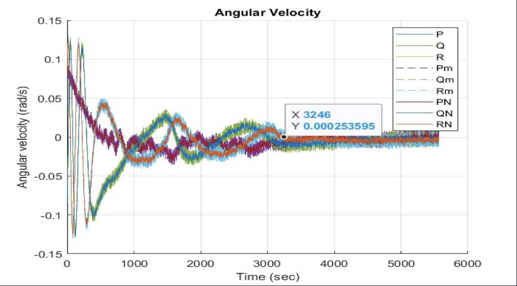
Detumbling, or reducing the satellite's angular velocities, is performed using the B-dot algorithm. This algorithm requires the instantaneous magnetic field vector and the instantaneous angular velocity. Both measurements are provided by an IMU. The satellite uses these vectors to compute the instantaneous rate of change of the Earth's magnetic field. The satellite then outputs a torque opposite to this derivative, thus stabilizing the satellite with reference to the Earth's magnetic field.
Magnetorquers have been selected as the attitude actuators for GASRATS over reaction wheels due to magnetorquers' comparative simplicity in design and algorithms, along with a lower price point.

Detumble Simulation Data
Nadir Pointing
Nadir pointing is orienting a specific face of the satellite towards the center of the Earth, such as the face with the transparent patch antenna. To determine the satellite's orientation for nadir pointing, GASRATS will run the tri-axial attitude determination (TRIAD) method. The TRIAD methods will need the sun vector, magnetic field vector, and GPS data to determine the satellite's orientation in the Earth-centered inertial (ECI) frame. After establishing its orientation in the ECI frame, the satellite can then point the antenna towards the Earth using the magnetorquers.
While nadir pointing, the satellite will only be able to communicate with the GAS Team's ground station for an average of 50 seconds each day, and by utilizing the other S-band-capable ground stations on the SatNOGS Network, for an average of 185 seconds per day. Nadir pointing is a minimum requirement for mission success because a link must be established between the satellite and the GAS Team's ground station. If time allows, the team may implement ground station tracking to increase the average transmission window.

Air Bearing for ADCS Testing
NASA's CubeSat Launch Initiative
In March 2024, GASRATS was announced as 1 of 10 CubeSats accepted to the 15th round of NASA's CubeSat Launch Initiative (CSLI). NASA CSLI is an incredible program that provides universities and non-profits a way for their CubeSat to get to space. The launch opportunity window for the round is 2025-2028. Once GASRATS has completed its critical design review, the CubeSat will be manifested for a flight approximately 12 months later. The GAS Team previously participated in CSLI with GASPACS, which was selected in 2013 and launched in 2021.

Credit: NASA-LSP

